
Reverting to the old ways
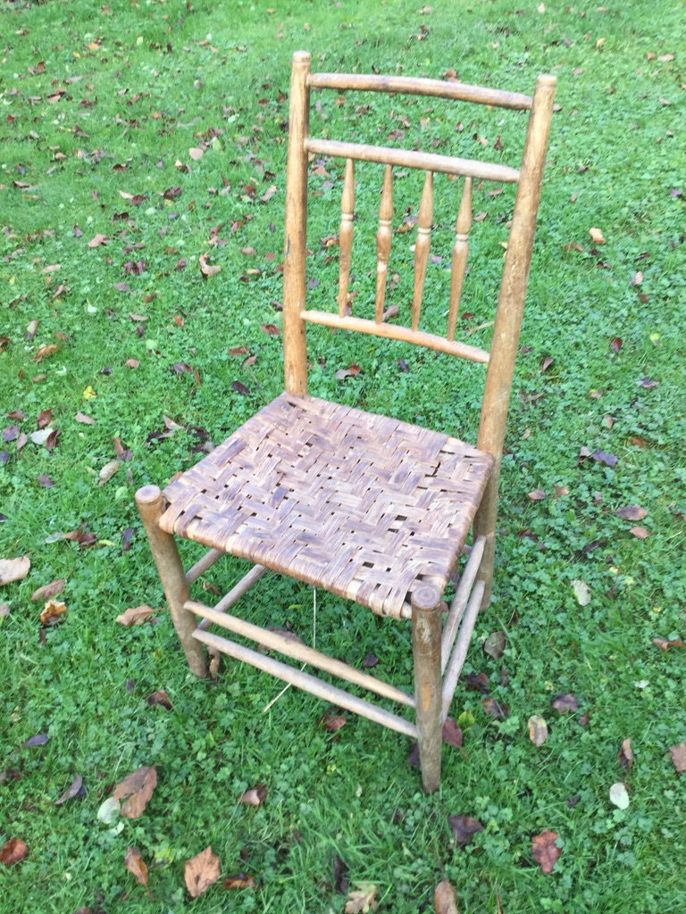
I have called this blog ‘A new Approach to Chair Assembly’ but in fact it is a description of how I reverted to the more usual method of assembling a frame chair, that is to assemble the front panel and the back panel first, and then join them. This is the approach I described in my first book, Green Woodwork which was published way back in 1989 and it is the way we assembled chairs on my courses for the first 10 years or so. Here is a photo of the chair made by Tamsin when she attended her first course in 1993, which is still in daily use.
Sometime in the 1990’s, I switched to the approach of assembling the two individual side panels and then joining them. This was described in books by the American green woodworkers, Drew Langsner and Roy Underhill, so following my desire to try out alternatives, I thought I’d give it a go. In the general scheme of things it is not a great difference and as it worked OK, I adopted this approach and I described it in my two subsequent books, Living Wood and Going with the Grain.
Time for a rethink
During the summer of 2020, I had time to consider this approach and decided to experiment during the few courses I was able to run due to coronavirus. The starting point was to place a completed chair onto a bench with props beneath the appropriate points where I knew the length of the components as described in my books. We start with one of the front legs flat on the bench. The front rungs are 45cm, while the back ones are 35cm. 45 minus 35 makes 10. By lifting the back of the chair by half this difference (i.e. 10 divided by 2, equals 5cm) the front and back rungs and rails will be vertical. I find to difficult to explain in words why this works but if you doubt me, try it out! Using the same reasoning, with the crest being 43cm (subtracting about 1cm for the bend), then that point should be lifted 1.5cm (half of 45 minus 42).
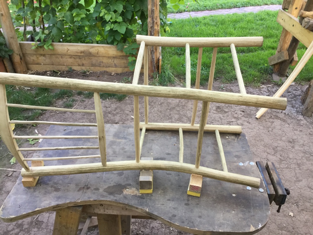
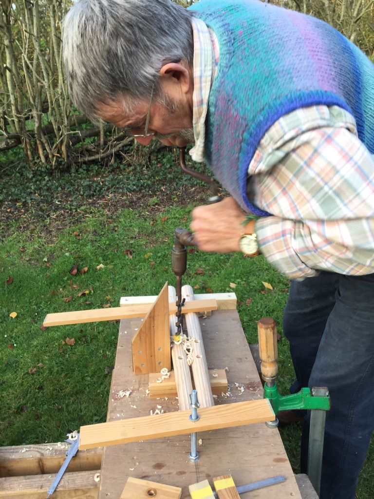
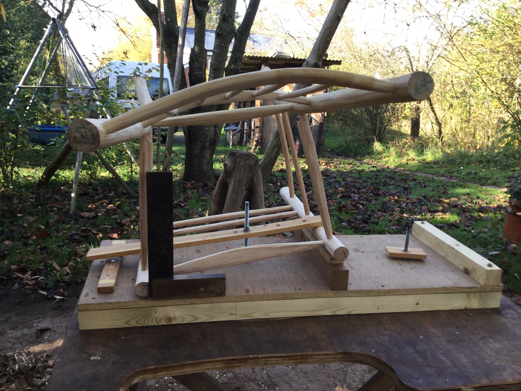
To cut a long story short (3 months of constant experimentation), I decided to build a ‘drilling platform’, which enabled me to fix various battens and insert a couple of bolts to hold the back legs in place during the drilling process. It needed three fixed points to locate the legs consistently (for the same reason that 3 legs are more stable than 2 or 4) . The breakthrough came when I abandoned one of the 5cm blocks illustrated above and substituted a block for the bottom of the leg as illustrated below. By placing a completed chair frame with its front leg at the same level as the drilling platform, I established the thickness of the new block by trial and error until the frame sat without wobble, with the front and back rungs vertical. With a new leg in a matching position it looked like this.
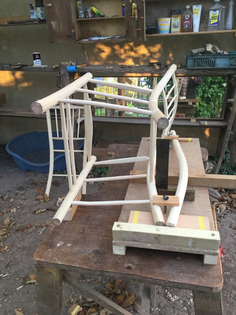
Now by replacing the assembled frame with the matching back leg it looked like this – something really quite elegant, I thought!
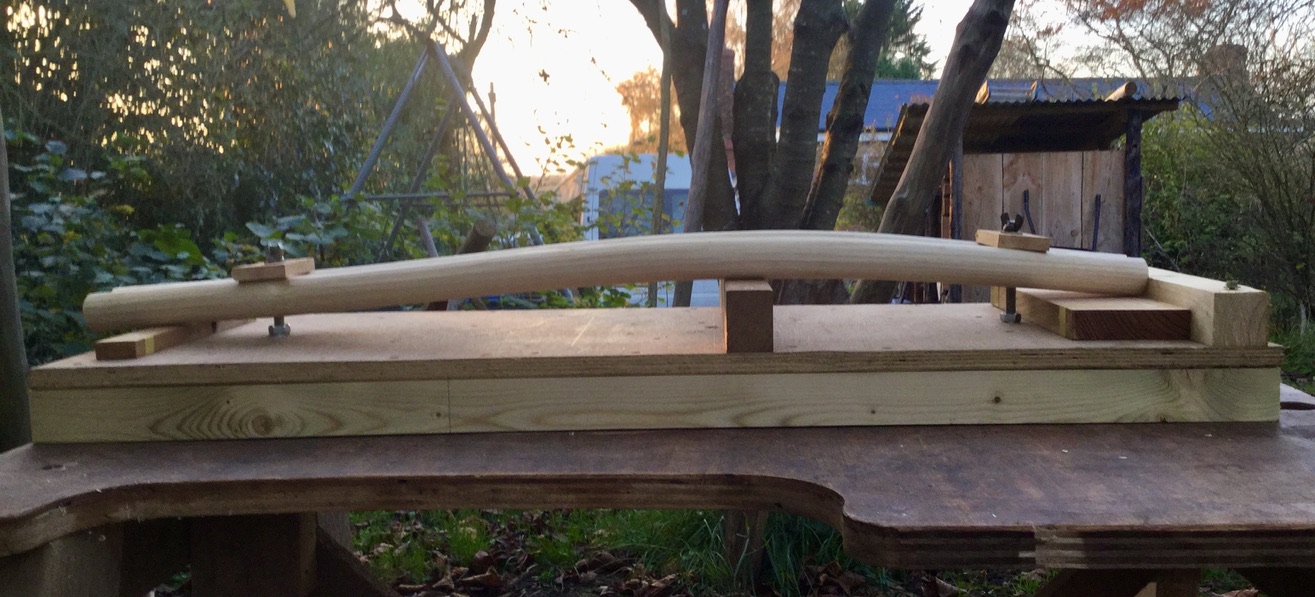
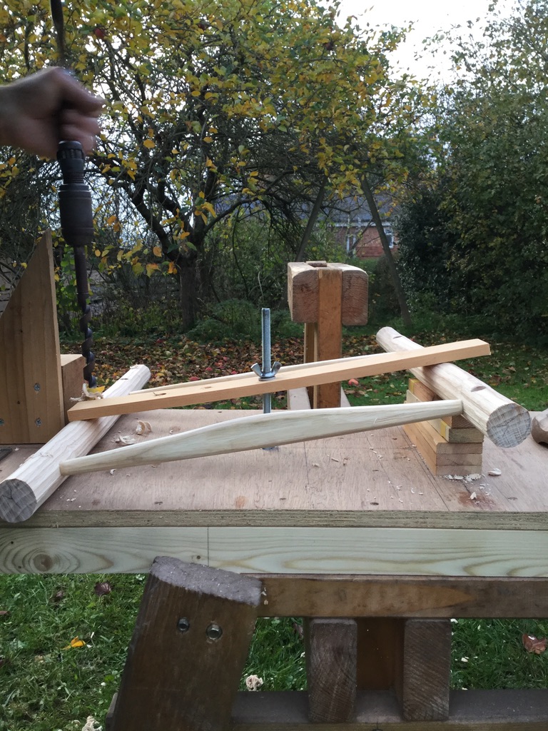
The mathematician within me then simplified it slightly by subtracting 15mm from each support, going from 15, 50 & 30 to 0, 35 and 15. Tamsin pointed out that not everybody has access to a planer-thicknesser, so I made use of some assorted bits of 12mm and 15mm batten. By moving the bottom block to 90cm from the top edge (the height of the hole for the crest), the legs were now able to simply rest on the top of the platform as shown below.
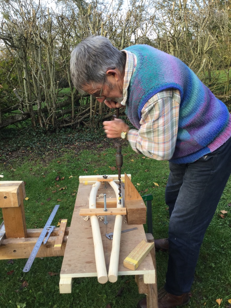
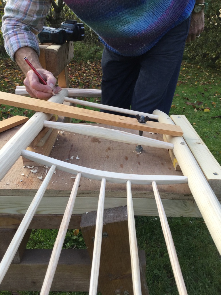
I had played about with the idea of rotating the legs slightly, so that the top two pairs of holes (for the curved crest & crossrail) could be drilled vertically. Eventually I settled for the old method of drilling them at an angle, such that one end of the crest is vertically above the other end (as described in Going with the Grain)
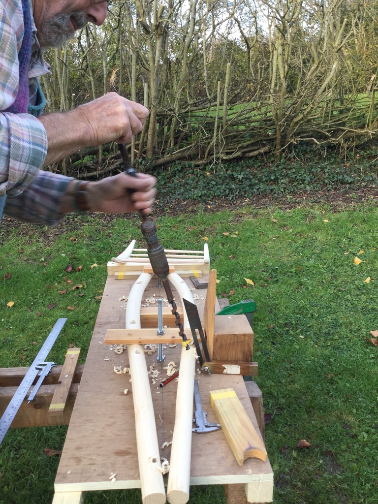
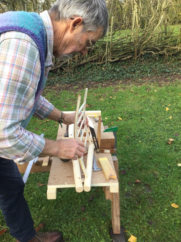
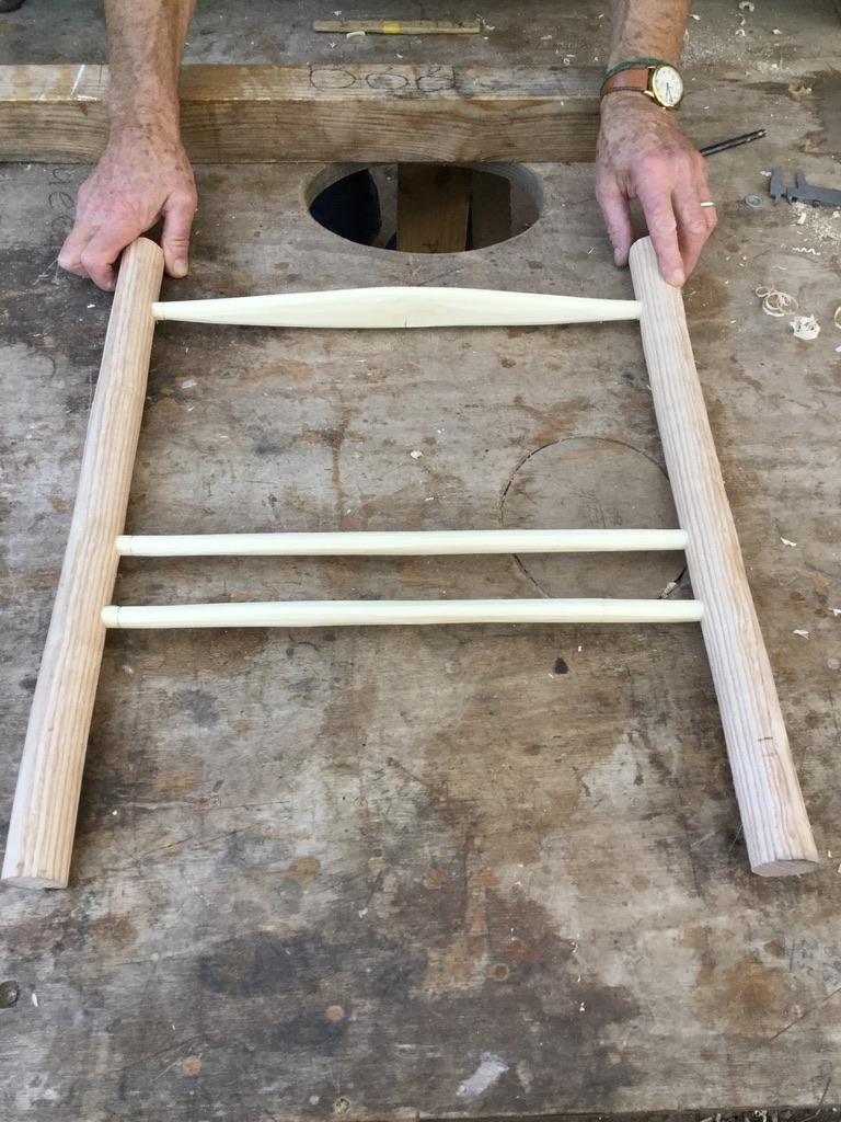
With these four holes drilled into each of the back legs, the back frame could then be assembled. The rear seat-rail and the back rung were squeezed into their holes using the same method I have used for the last 20 years: the tenons being shaped with a 16mm tenon cutter while they were green, then dried so they shrink to an oval, then squeezed into a 14mm hole. Because the top two components (crest & cross-rail) have been steam-bent to a curve, it helps to shape their tenons with a 9/16″ tenon cutter. This is the equivalent of 14.3mm, so this will still result in a tight joint but not ultra-tight like the lower components. It is not too difficult now to assemble this back panel single-handed, while checking that it isn’t twisted out of square. (See what I mean below with the front panel)
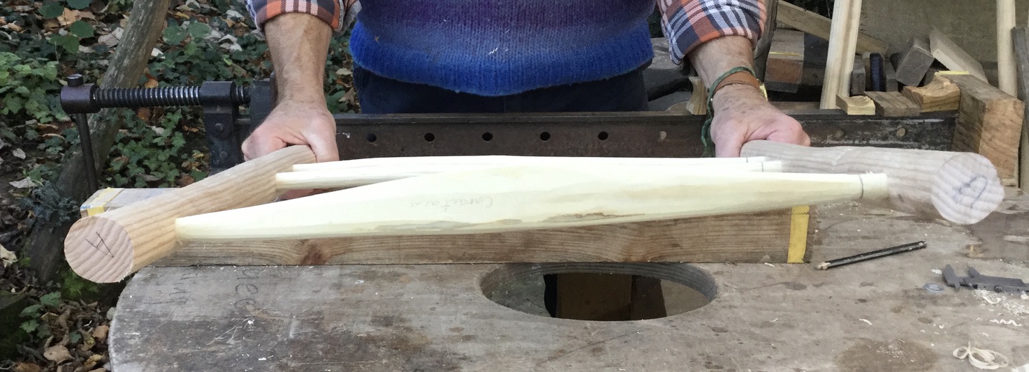
Assembling the front panel is now straight-forward.
As with the back panel, check that the frame is not twisted when you squeeze it together.
To deal with the splayed shape of the chair, it is now a matter of supporting each panel at an angle, so that the remaining holes can be drilled vertically. Using the calculations at the beginning of this blog (45 – 35 divided by 2 equals 5cm) the back panel needs to be lifted on one side by 5cm. In practice, what I did was to lift the lower side by 15mm so that it was clear of the bench. Then I lifted the other side with a pile of laths (3x12mm plus 2x15mm making 66mm in total) resulting in a height difference of 51mm (that extra mm is not significant!). These bits of lath are 18cm long, the same as the spacing between the side rungs) with their ends positioned beneath the holes for seat-rail and the centre rung, as shown below.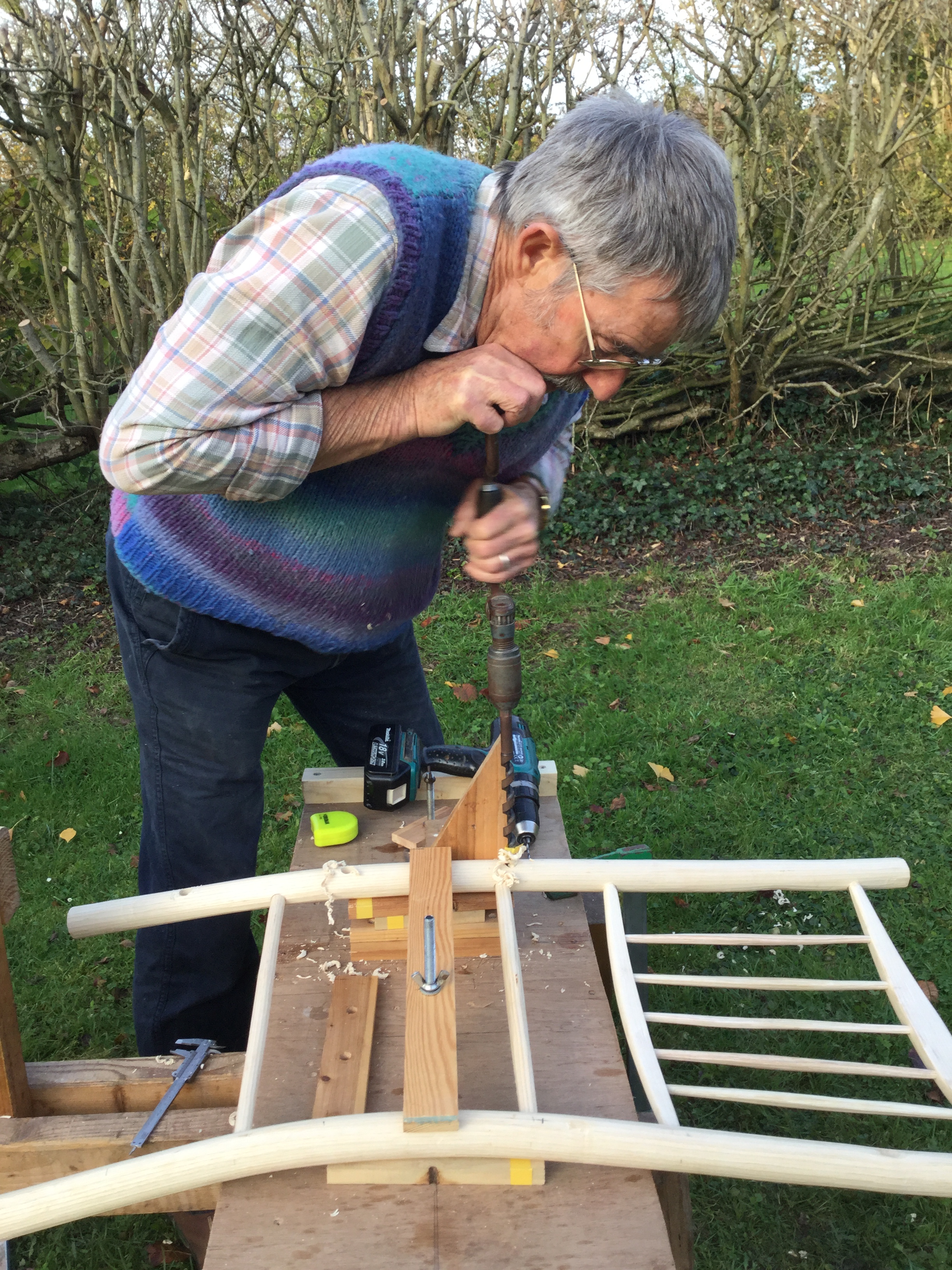 You need to make sure that you are drilling just into the correct leg in this position, then change the tilt for drilling into the other leg.
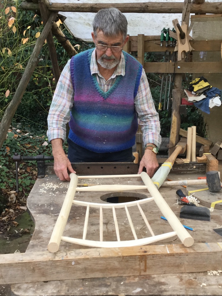
Here is the back panel with 6 holes drilled for the side rungs and seat-rails, with the correct splay.
Now to drill into the front panel. I could see no obvious calculation for the lift of the front panel but because it is wider than the back panel it needs more lift. I drew it on some graph paper, which gave me 65mm, so here’s a completed chair in one of the earlier experiments to check that’s right .
Using the same bits of lath, I lifted one side by 65mm (well, 3×12 plus 2×15 equals 66)
Obviously you need to remember to drill the correct leg in order to get the correct splay. If you are like me, you will have to get it wrong at least once for the lesson to stick!
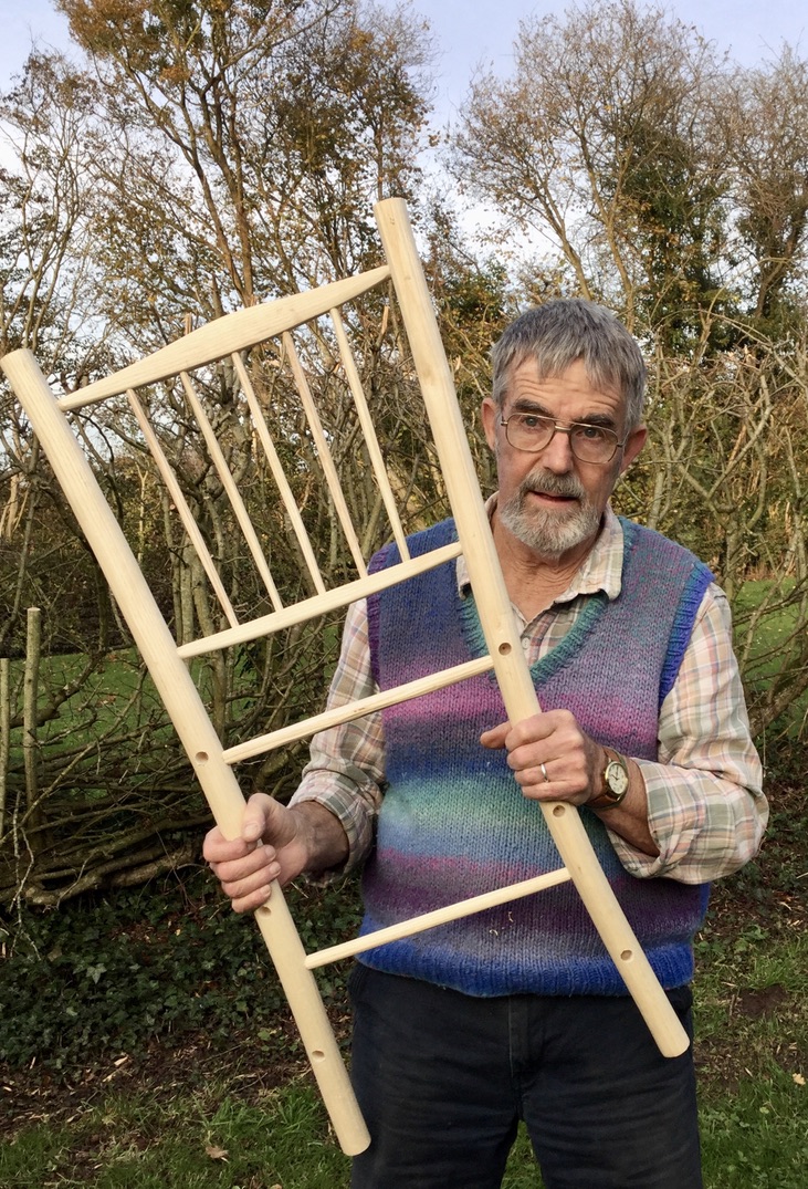
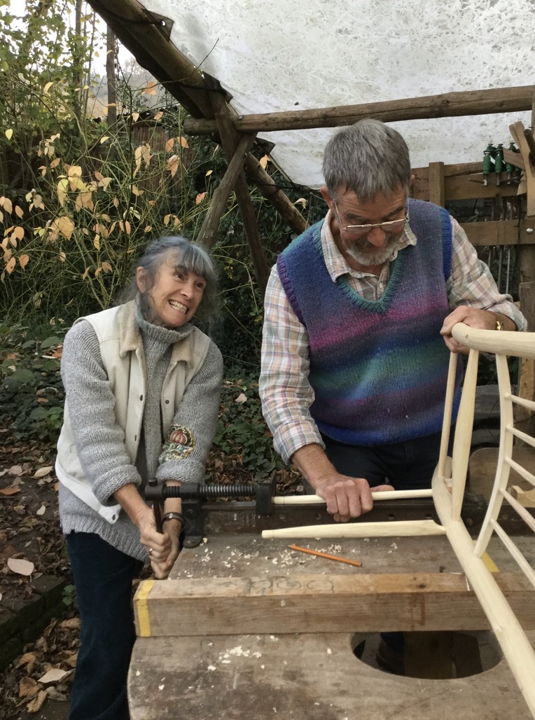
Once both panels are drilled, I strongly advise you to get some help to squeeze the whole frame together!
I’ve had 8 weeks to finish this blog but in the meantime, things have changed, so I’ll post it now, then do an update another time!
